How to Use an NPS Pipe Size Chart to Verify a Piping Drawing
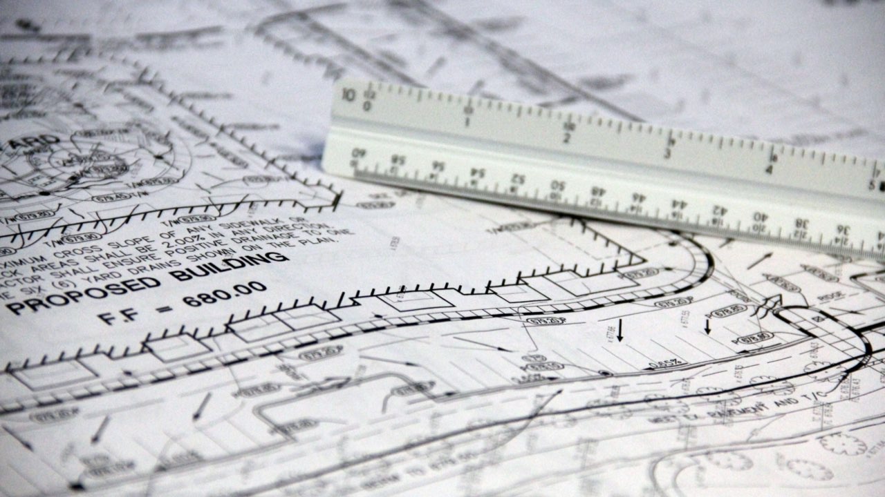
Piping drawings contain a lot of information in a compact format, and one of the most common sources of error during procurement or fabrication review is misreading what a pipe size annotation actually means. An NPS designation on a drawing is not a direct physical measurement — it’s a reference to a standardized system of dimensions that you need a chart to translate into actual outside diameter and wall thickness values. The process of doing that translation correctly is straightforward once you’ve done it a few times, but it’s worth walking through carefully.
Step One: Identify What the Drawing Is Specifying
A pipe size annotation on a drawing will typically appear in one of a few formats. “NPS 3, Sch 40” is common in US-standard drawings. Some drawings will show just the NPS designation and material specification without an explicit Schedule. Others will list both NPS and the outside diameter explicitly — in which case the chart is used to verify rather than derive the OD.
Before going to the chart, confirm which standard the drawing is using. ASME B36.10M covers carbon steel pipes. ASME B36.19M covers stainless steel. The NPS designations and outside diameters are the same across both standards, but the available Schedule numbers and corresponding wall thicknesses differ. Knowing which standard applies tells you which column of the chart is relevant for wall thickness lookup.
Step Two: Confirm the Outside Diameter
Look up the NPS designation in the chart to get the outside diameter. This step matters even when you think you know the OD, because it catches transcription errors on drawings.
The outside diameter is fixed by NPS designation and doesn’t change with Schedule or wall thickness. Common values to memorize for quick cross-checks:
- NPS 1 = 1.315 in OD (33.4 mm)
- NPS 2 = 2.375 in OD (60.3 mm)
- NPS 3 = 3.500 in OD (88.9 mm)
- NPS 4 = 4.500 in OD (114.3 mm)
- NPS 6 = 6.625 in OD (168.3 mm)
- NPS 8 = 8.625 in OD (219.1 mm)
If the drawing lists an OD that doesn’t match the NPS designation from the chart, there’s an error somewhere — either in the drawing annotation or in the standard being applied. Don’t proceed with procurement until this is resolved.
Step Three: Look Up Wall Thickness by Schedule
Once OD is confirmed, locate the wall thickness for the specified Schedule. This is where a full NPS pipe size chart becomes essential, because Schedule numbers don’t map to a single wall thickness across all pipe sizes.
Schedule 40 for NPS 2 has a wall thickness of 3.91 mm. Schedule 40 for NPS 6 has a wall thickness of 7.11 mm. The Schedule number represents a pressure rating formula, not a fixed dimensional increment — so you cannot derive wall thickness from Schedule number alone without knowing the NPS.
Cross-check the wall thickness from the chart against any tolerance or pressure rating requirements called out in the drawing notes or the project specification. If the drawing specifies a minimum wall thickness rather than a Schedule, find which Schedule meets or exceeds that minimum for the relevant NPS.
Step Four: Check Fitting Compatibility
Fittings, flanges, and valves are also sized by NPS, and they’re designed to connect to the fixed outside diameter of the corresponding pipe. A butt-weld fitting specified as NPS 3 will fit an NPS 3 pipe regardless of Schedule, because the outside diameter is the same. The inside diameter of the fitting is typically machined to match the wall thickness of a specific Schedule — if the pipe Schedule and fitting Schedule differ significantly, the inside diameters may not align, which creates a flow restriction or a mismatched weld preparation.
When reviewing a drawing that includes fittings, confirm that the fitting NPS matches the pipe NPS at each connection point, and check whether the drawing specifies that fittings should match the pipe Schedule. If it doesn’t specify, standard practice for pressure piping is to match Schedule between pipe and fitting.
Step Five: Flag DN References and Convert If Needed
If the drawing mixes NPS and DN (metric nominal diameter) references — which happens on international projects using both US and European components — use the chart to confirm that the DN and NPS designations at each connection point correspond to the same outside diameter.
DN50 and NPS 2 share the same OD of 60.3 mm. DN80 and NPS 3 share the same OD of 88.9 mm. Where both systems appear on the same drawing, they should always refer to the same physical dimension at any given connection. If a DN80 flange is being specified to connect to an NPS 4 pipe, the outside diameters don’t match — DN80 is 88.9 mm, NPS 4 is 114.3 mm — and that’s a problem that needs to be caught before fabrication.
Common Errors This Process Catches
The verification steps above are designed to catch the most frequent drawing-related pipe size errors:
- NPS annotation that doesn’t match the listed OD (transcription error)
- Schedule number used as if it were a wall thickness (dimension error)
- Fitting NPS that doesn’t match pipe NPS at a connection (selection error)
- DN and NPS designations mixed at the same connection with different ODs (standards confusion)
None of these errors are exotic — they appear regularly in real projects, particularly when drawings pass through multiple hands or are converted between standards. Running through the chart verification steps for each pipe segment in a drawing adds time at the review stage but removes far more time from the correction process later.